BLOG

What functions should an excellent hot runner temperature controller have

0616

A high-quality hot runner temperature control box is a key device to ensure the stable operation of the hot runner system. Its functional design needs to take into account multiple requirements such as precision, safety, convenience, and compatibility. The following explanation is provided from the dimensions of core functions, auxiliary functions, and extended features:

High-precision temperature control function

1. Precise temperature control and stable output

Many users are concerned about the control accuracy of the temperature control box and may request a control accuracy of ±0.5℃ or even ±0.1℃. However, in actual use, it is known that plastics are amorphous and do not have a fixed melting point. As long as the temperature control accuracy meets the process requirements of the hot runner system, it is sufficient. Considering the current hot runner processing technology and the system consistency of the final product of the hot runner system, it is already very excellent for the hot runner temperature control box to control the temperature accuracy within ±1℃. The claim of ±0.1℃ control accuracy is purely that of an outsider. Currently, there are very few industrial temperature control devices in the world that can achieve a temperature range of 0-500℃ and a control accuracy of ±0.1℃. In addition, the current hot runner temperature control system mainly uses thermocouples to measure temperature. Considering the working characteristics of thermocouples and the variable temperature environment in the injection molding workshop, it is basically impossible to achieve a temperature control accuracy of ±0.1℃.

2. Multi-channel independent control

Supports 8, 16, 32 and other multi-channel temperature control (selectable according to requirements), each channel can independently set temperature, heating power and alarm threshold, meeting the zonal temperature control requirements of complex hot runner systems (such as multi-cavity molds).
The channels are designed with electrical isolation to avoid mutual interference and improve system stability.

Safety protection and fault diagnosis function

1. Multiple safety protection mechanisms

  • Over-temperature protection: When the actual temperature exceeds the set value (such as 10℃ or more), the heating power is automatically cut off and an audible and visual alarm is issued to prevent the heating element from burning out or the plastic melt from carbonizing.
  • Open-circuit protection: Real-time monitoring of the connection status of the thermocouple (temperature sensor). If a disconnection or poor contact occurs, heating is immediately stopped and the faulty channel is indicated to avoid "false temperature" causing production accidents.
  • Overload protection: Built-in circuit breaker and overload protector. When a short circuit or other abnormal current occurs in the circuit, the power is quickly cut off to ensure the safety of the equipment and personnel.
  • Fanless normal operation design: The injection molding workshop environment is harsh, and equipment maintenance frequency is low. The cooling fan of the hot runner temperature control box often fails. Therefore, the temperature control box must be able to work in high-temperature environments without equipment failure due to high temperatures, affecting production.

2. Intelligent fault diagnosis and alarm

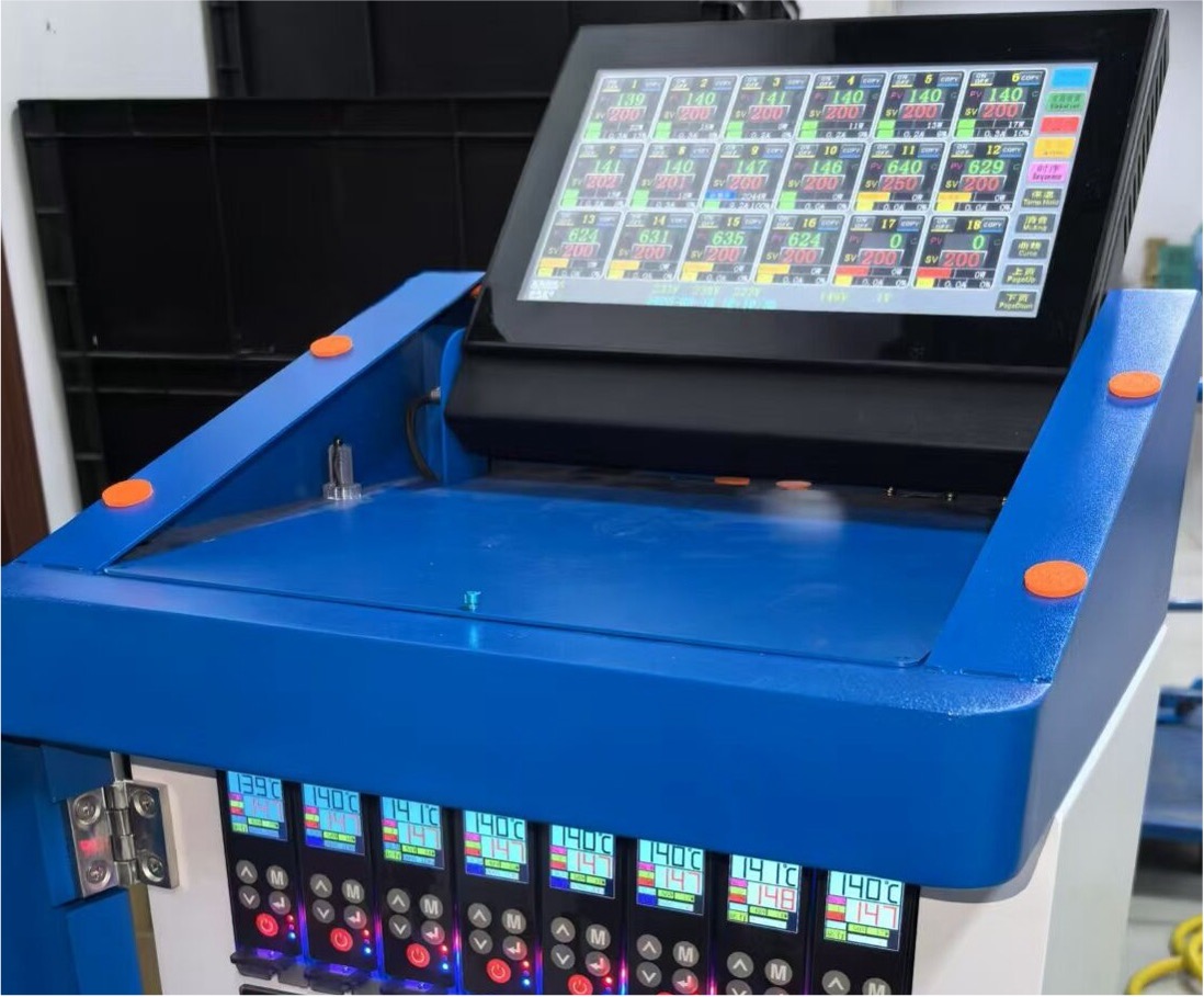
  • Real-time fault display: Through the display screen (such as LCD or touch screen), various control information such as temperature, voltage, power, current, and other fault types (such as over-temperature, open-circuit, heating out of control, etc.) and corresponding channels are displayed intuitively, facilitating quick problem location. In today's information age, using a few LED digital tubes to display alarm information is far from enough. It will greatly affect the production efficiency of injection molding factories.
  • Diversified alarm methods: Supports audible and visual alarms (beeper + indicator light), screen pop-up prompts. Some high-end models can transmit alarm information to the PLC or upper computer system through interfaces such as RS485 to achieve remote monitoring.

Convenient operation and humanized design

1. Intuitive human-machine interaction interface

  • Graphical display screen: Equipped with a large-sized color touch screen or digital display screen, supporting real-time display of temperature curves, parameter setting (such as temperature, heating time, power percentage), and historical data query.
  • Menu-based operation: Simple interface layout, supporting password permission management (distinguishing between administrator and operator permissions) to prevent unauthorized personnel from mistakenly modifying parameters.

2.Flexible parameter setting and storage

  • Multiple recipe storage: It can store more than 10 sets of temperature control parameters for different products (such as temperature setting values corresponding to different molds). When changing products, one-click call can be made to reduce debugging time.
  • Manual / automatic mode switching: It supports manual adjustment of heating power (suitable for the debugging stage) and automatic PID control (production stage) to meet the needs of different scenarios.

3. Convenient maintenance and debugging functions

  • Self-diagnostic test: It supports self-check at startup (checking the circuits and sensor connections of each channel), and some models can manually trigger heating output test, which is convenient for maintenance personnel to troubleshoot hardware faults.
  • USB or serial port data export: Temperature data and fault records can be exported to a USB drive or computer for production traceability or data analysis.

High-efficiency energy-saving and compatibility design

1. Energy-saving optimization function

  • Intelligent power regulation: Automatically adjust the heating power according to the temperature deviation (such as full power heating at low temperature and gradually reducing the power as the set temperature is approached), reducing energy waste.
  • Standby sleep mode: A standby temperature can be set during non-production periods to keep the system in a preheated state while reducing energy consumption.

2. Wide compatibility and expandability

  • Compatible with multiple heating elements: Supports various thermocouples (such as J-type, K-type, etc.)
  • Communication interface expansion: Standard interfaces include RS485, USB, Ethernet (such as Modbus, TCP/IP protocols), etc., which can be integrated with injection molding machine control systems and MES systems to achieve automated production and remote monitoring.
  • Modular design: Some temperature control boxes adopt a modular structure, allowing the number of channels to be increased or decreased according to needs, or faulty modules to be replaced, reducing maintenance costs.

Other auxiliary functions

1. Temperature curve recording and analysis

Real-time recording of temperature change curves for each channel, supporting historical data query (such as temperature fluctuation records for the past 7 days or 1 month), facilitating analysis of production stability or optimization of process parameters.

2. Anti-interference design

  • Internal circuits adopt EMC (electromagnetic compatibility) design to reduce the impact of external electromagnetic interference on temperature control accuracy and avoid interference from the equipment itself to other electronic devices.

3. Environmental adaptability

  • Capable of wide temperature operation (such as -10°C to 60°C), adapting to temperature fluctuations in factory workshops. Some models also support moisture-proof and dust-proof designs (such as IP54 protection level), extending the equipment's service life.


Analysis Of Thermocouple Principles

0609

Working principle of thermocouples

Thermocouples operate based on voltage signals rather than resistance signals

1

Correct conclusion:

A thermocouple with a normal resistance value is not necessarily a thermocouple that can work properly, but a thermocouple with an abnormal resistance value is definitely a damaged thermocouple.

Many people think:

Use the resistance range of a multimeter to test the thermocouple to determine its quality.

wrong0606

Thermocouple: It is a sensor that converts temperature changes into electrical signals.

The temperature made using the Seebeck effect
The sensor is called a "thermocouple".

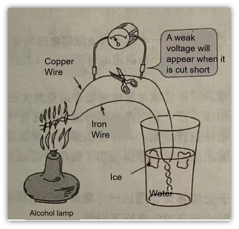
Seebeck effect: When two different metal wires are connected, a temperature difference is created at both ends of the connection, resulting in the generation of voltage.

thermocouple-0606-en


Two different metals


There is a temperature difference

Working diagram of thermocouple measuring instrument

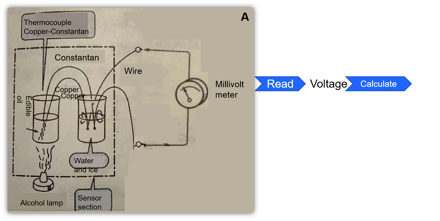
Illustration of the temperature measurement principle of thermocouples

thermocouple-0606-1-en

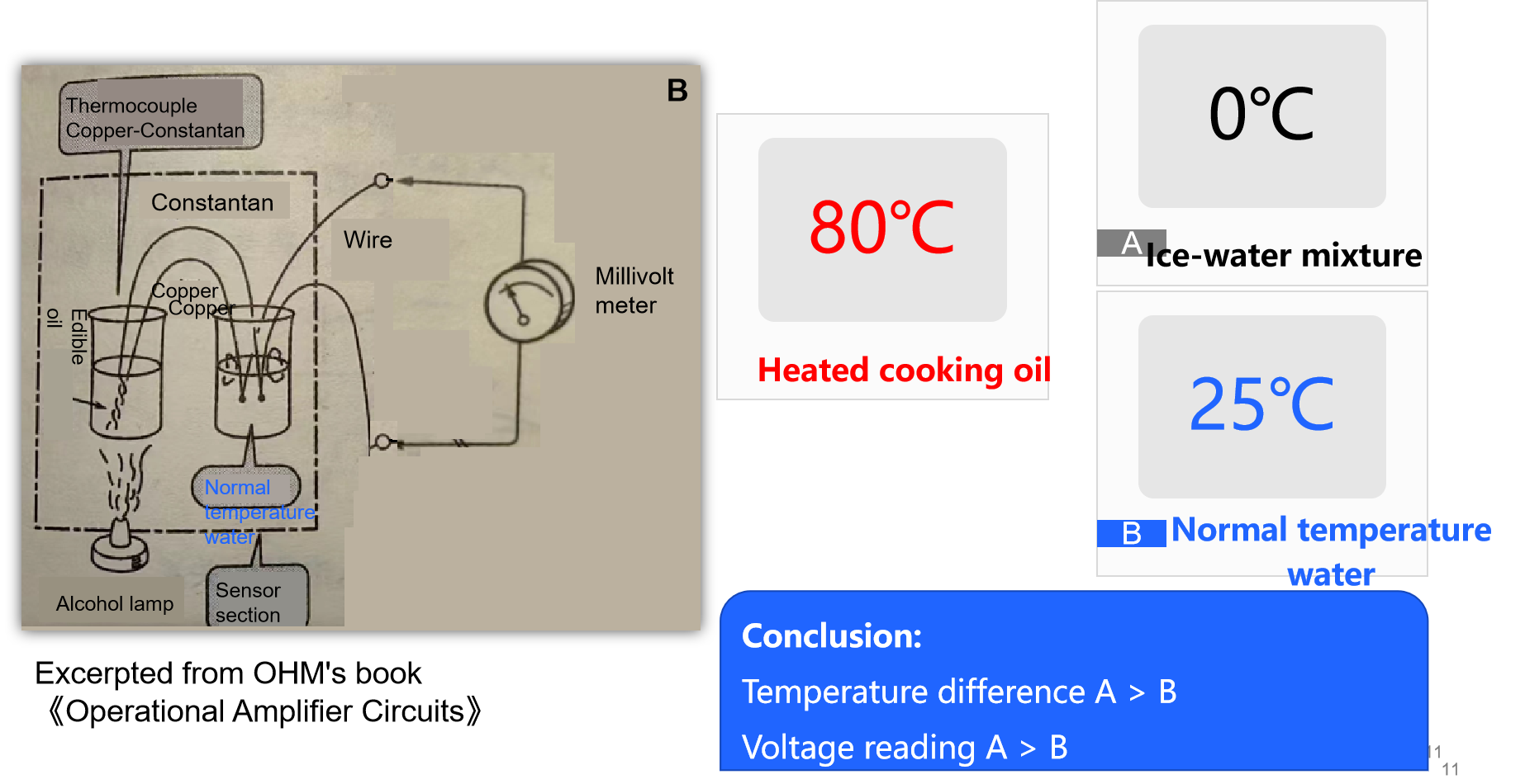
Excerpted from OHM's book 《Operational Amplifier Circuits》

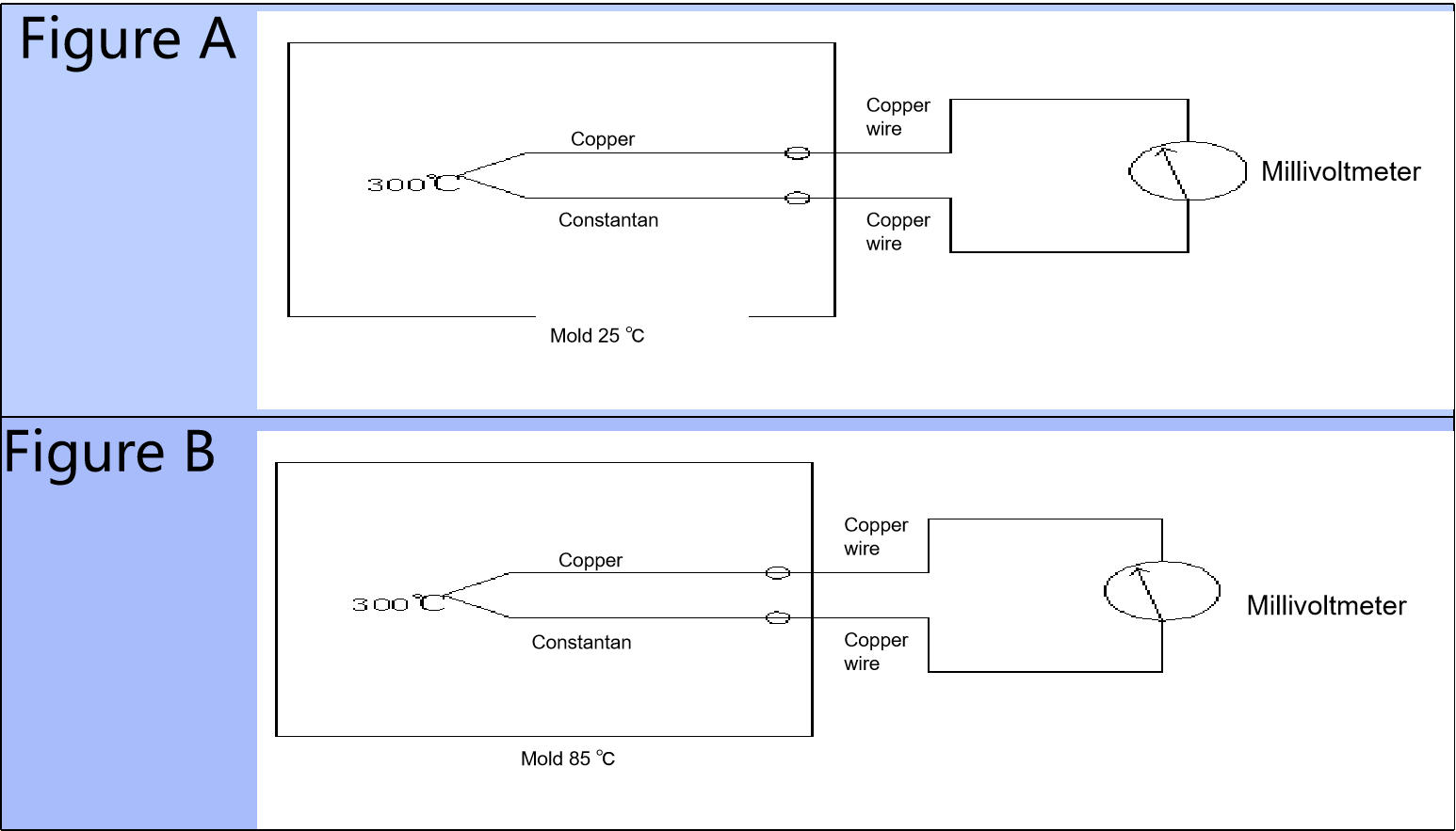
Suppose the ice-water mixture is replaced with normal-temperature water. What would be the result of the voltage?

thermocouple-0606-2-en

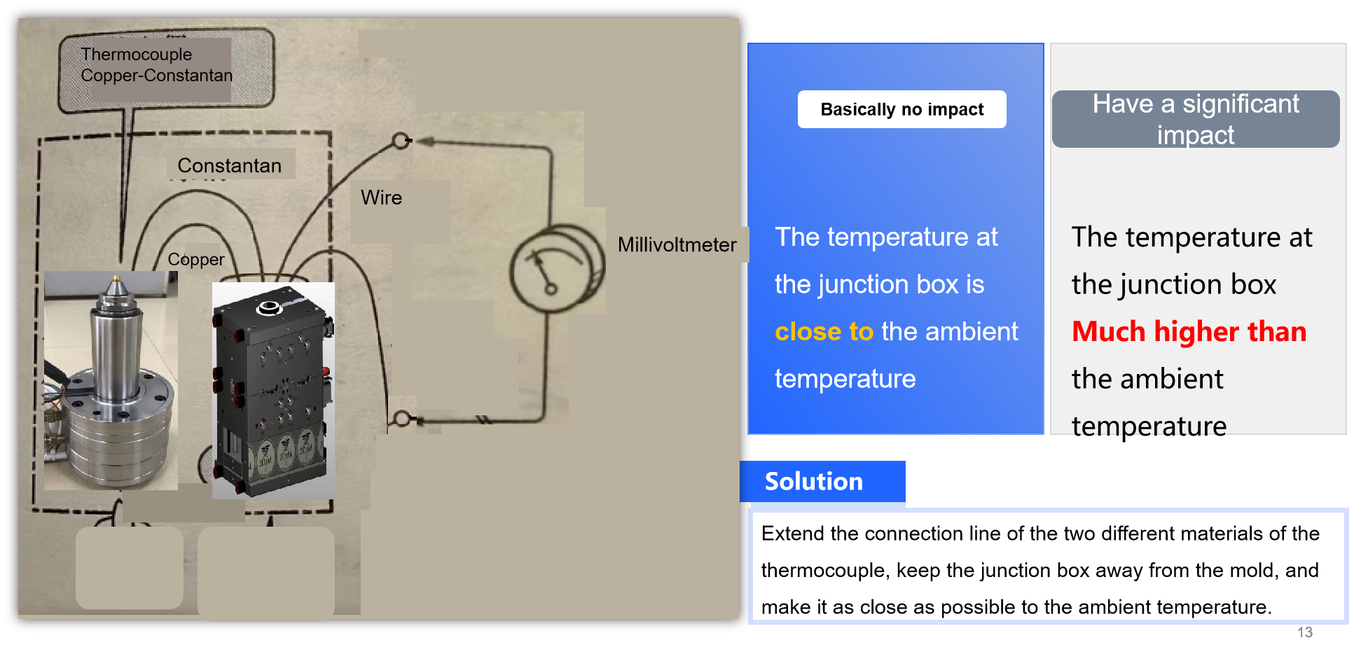
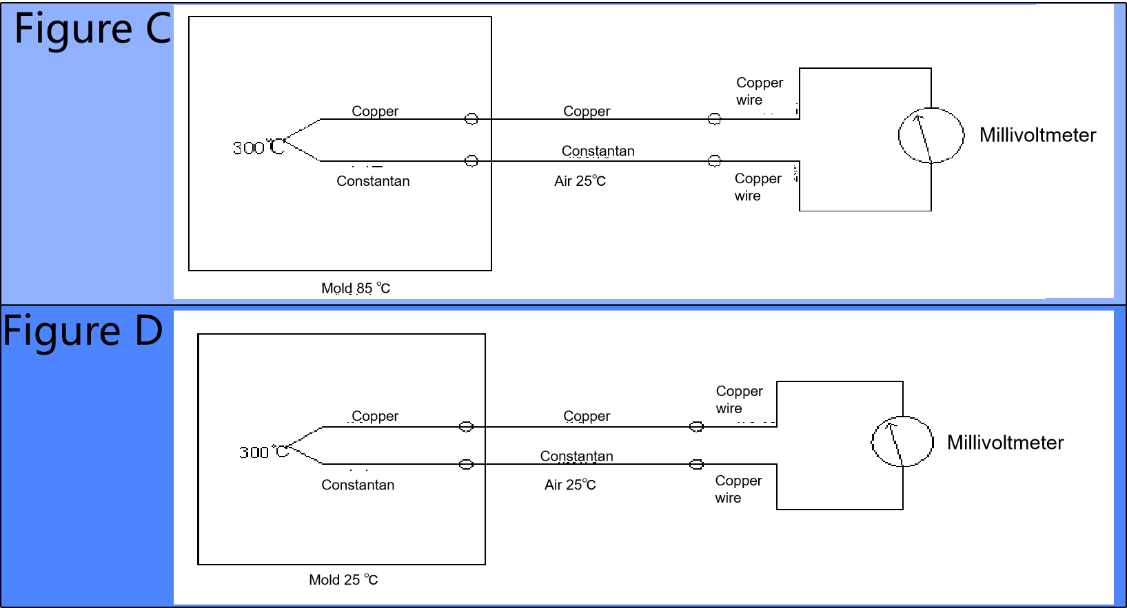
Hot runner analogy

thermocouple-0606-3-en

Think: Sort the signal sizes of the millivoltmeter in the following four figures

thermocouple-0606-4-en
thermocouple-0606-5-en

Hot Runner Technology (2/2)

0527

Advantages

  • Shortened Cycle Time:Since the runner does not need to be demolded,cooling time is reduced,thereby shortening the cycle time.
  • Cost Reduction:Savings are made on the demolding ,transportation ,recycling ,storage , and pre-drying costs of the runner.
  • Reduced Injection Volume:The elimination of the runner reduces the injection volume,allowing the use of smaller injection molding machines.
  • Decreased Clamping Force and Plasticizing Capacity:The reduction in runner area decreases the projected area,thereby reducing the clamping force and plasticizing capacity.
  • High Gate Design Flexibility:The hot runner system provides greater flexibility in the geometric design of the gate.
  • Cooling and Pressure Advantages:Cooling is no longer an issue in the hot runner system,and lower pressures can be used.
  • Reduced Melt Shear Stress:Increasing the cross-sectional area of the runner can reduce melt shear stress.
  • Support for Advanced Technologies:Hot runner technology is the foundation for advanced techniques such as stack molding,sandwich molding,hot plastic resin foaming injection,and multi-color injection molding.
  • Improved Molding Quality:Effective design of the thermal insulation area in contact with the surface,selection of appropriate materials,and individual cooling of gates can increase holding pressure time,improve the quality of molded parts ,and reduce part shrinkage.

Limitations
  • High Mold Cost:Hot runner molds are more expensive,especially those with needle valve shut-off systems.
  • High Energy Costs:The energy cost of hot runner molds is higher than that of traditional molds.However,considering the energy required for the main and sub-runners in a cycle,the hot runner system may be more advantageous.
  • High Operation and Maintenance Costs:The operation and maintenance costs of hot runner systems are higher and require specially trained personnel.
  • Increased Complexity:Hot runner molds are more complex than traditional molds and require careful operation and high precision.
  • High Thermal Equilibrium Requirements:To minimize thermal and mechanical damage to the melt,a high degree of thermal equilibrium must be maintained,and the equipment temperature must be strictly controlled.
  • Material Thermal Degradation Risk:The residence time of the material in the hot runner may exceed the allowable value,leading to thermal degradation.The type of heating(internal or external)may also cause material thermal degradation.
  • Part Wear and Corrosion:Parts that are highly susceptible to wear and other hot runner components,such as nozzle tips and thermocouples,should be easily inspectable and replaceable.Metal surfaces are prone to chemical corrosion and require a protective layer.
  • Difficulty in Color Change:Stagnant areas in the hot runner make color changes more difficult and may cause material degradation.
  • Thermal Insulation at Gate Area:Thermal insulation should be achieved in the gate area to prevent thermal degradation or unwanted material cooling.
  • Mechanical Stress on Miniaturized Parts:Miniaturized hot runner parts(such as micro-molding)can lead to high mechanical stress,especially for hot runner nozzles with high processing temperatures and high internal pressures.The lack of effective data makes the design of reliable parts complex.

Hot Runner Technology (1/2)

0527

Definition and Basic Principle

  • The hot runner system is a connecting system between the injection molding machine and the mold cavity,embedded in the mold.It allows the plastic melt to remain in a molten state for at least one cycle or more,preventing the melt from solidifying in the runner,which is commonly referred to as"runnerless molding."
The melt flow system acts like a connecting pipe.Regardless of the cross-sectional area and length of the channel,the melt can quickly fill the space around the gate,thus enabling the simultaneous filling of multiple cavities.
Key Considerations

  • Thermocouple Placement:Thermocouples should be placed in areas where the maximum temperature can be measured,i.e.,the region closest to the heat source. Internal Pressure Load:The allowable internal pressure load as a function of temperature is particularly important for hot runner nozzles,but relevant data is difficult to obtain.
  • Gate Cross-Section Design:If the surface of the molded product only allows for a very small gate mark,the gate cross-section should be designed to be smaller,but this will increase.

Summary
​Hot runner technology offers significant advantages in injection molding, such as shortened cycle times, cost reduction, and improved molding quality. However, it also has some limitations, including high mold costs, complex operation and maintenance, and high thermal equilibrium requirements. In practical applications, it is necessary to comprehensively consider these factors to fully leverage the advantages of hot runner technology while minimizing the impact of its limitations.

Our Company Excelled at CHINAPLAS 2025 International Rubber & Plastics Exhibition, Achieving Remarkable Success

0420

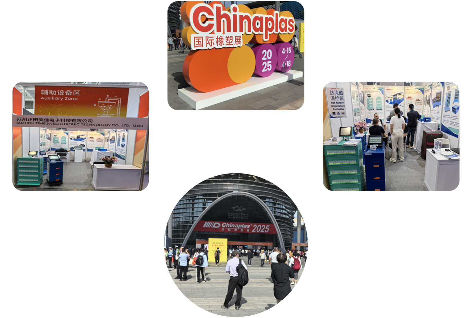
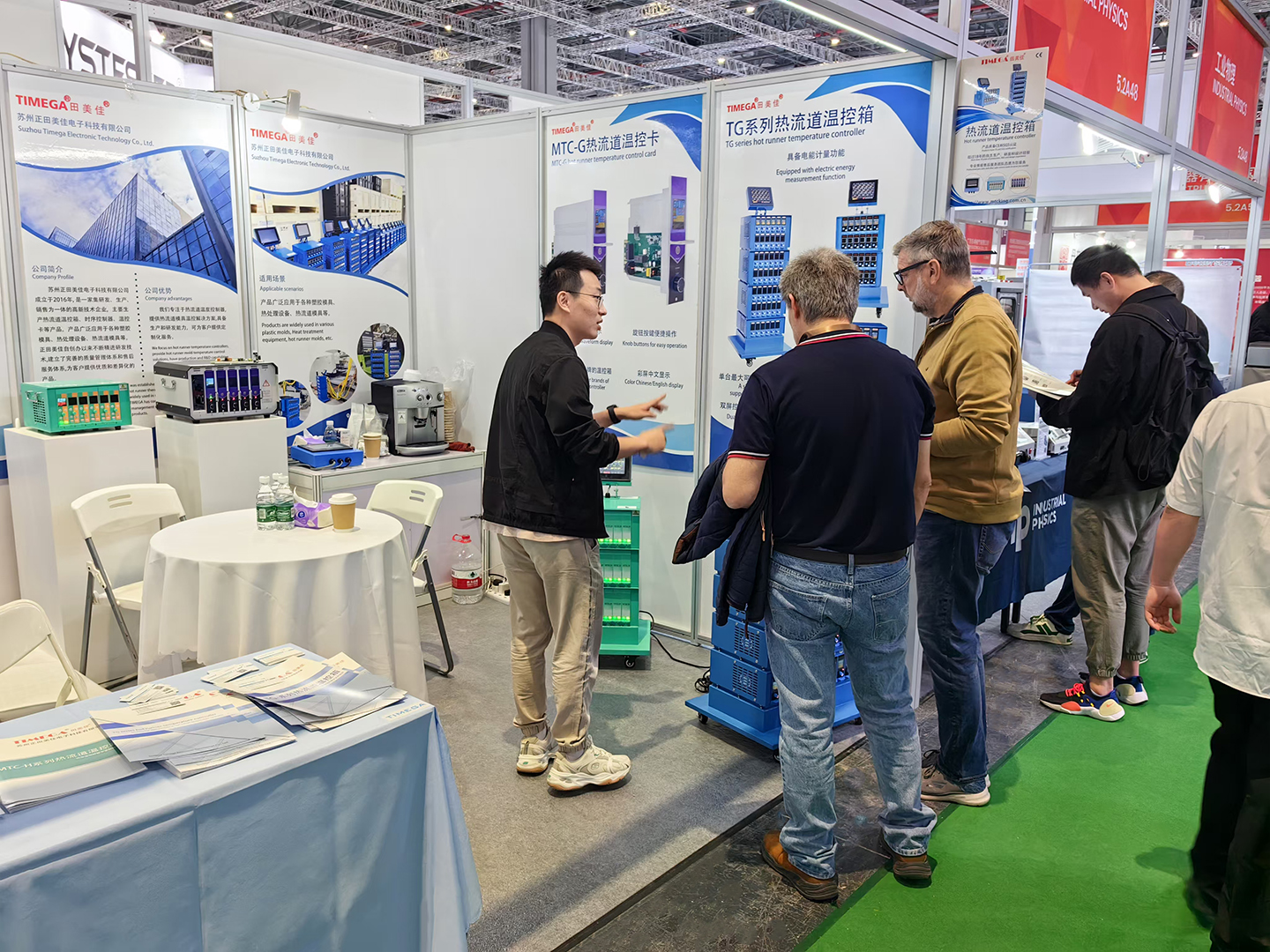
From April 15 to 18, 2025, the highly anticipated "CHINAPLAS 2025 International Rubber & Plastics Exhibition" was held grandly at the Shenzhen World Exhibition & Convention Center. Themed "Innovation · Collaboration · Co-creating Sustainability", this landmark event—a premier showcase of cutting-edge plastics and rubber technologies in Asia—drew global buyers and industry leaders. Our company actively participated in the event and delivered exceptional results.

During the exhibition, our meticulously designed booth attracted significant attention from visitors. Highlighting our self-developed range of hot runner temperature controller , hot runner temperature control cards, and sequence controllers, we showcased products that stood out for their superior performance, innovative design, and deep commitment to sustainable development practices among numerous exhibits. These products became focal points at our booth, drawing crowds of professionals who stopped to inquire and engage.

During the four-day exhibition, our booth was bustling with visitors. We engaged in in-depth and productive exchanges with attendees from many countries and regions around the world. From industry giants in developed countries in Europe and America to promising enterprises in emerging markets in Asia and Africa, there was significant interest in our company's products. Through on-site product demonstrations, technical presentations, and one-on-one business negotiations, we not only showcased our technological capabilities and innovative achievements in the hot runner temperature control field to the world but also reached preliminary cooperation intentions with several internationally renowned companies.

0420-1

Overview of Hot Runner 2

1101

         The application of hot runner technology has some obvious advantages, mainly the reduction in raw material waste and the ease of achieving automation in injection processing. In many cases, the production volume of large products is achieved by shortening the injection cycle or adopting other beneficial technologies. Some mold designs have been simplified. Injecting certain large-sized products would be difficult, or even impossible without hot runner technology. Only by using hot runner molds can cost-effective production be possible. In mass production of products, hot runner technology can achieve low costs. However, a basic prerequisite is the correct selection of the hot runner system. If the wrong choice is made, the opposite effect will occur. Some negative effects of hot runner technology during processing stem from misconceptions. For example, arbitrarily selecting nozzles; believing exaggerated claims about optimal parameters and durability, choosing cheap nozzles; using nozzles manufactured by small workshops; unskilled operation; lack of skills and understanding of physical phenomena in plastic processing; lack of reasonable strategies to reduce costs; also due to the poor performance of early hot runner systems. Hot runner manufacturers are aware of the significance of considering these situations and actively provide users with information on the performance of hot runner operations and correct selection. They offer the best explanations regarding relevant components and often take responsibility for system selection.
       No single hot runner system can be suitable for all plastic materials and all types of injection molded products. The range of variation in rheological and thermal properties of thermoplastics is very wide. This means that a dedicated hot runner system may be suitable for one type of thermoplastic but less so for others, and cannot suit all materials. Further improvement in the operation of hot runner systems depends on numerous factors such as injection volume and rate, flow path length, mold cavity shape, and plastic coloration. There are certain limitations in applications for heat-sensitive plastics, shear-sensitive plastics, plastics with flame-retardant additives, plastics with fibers and reinforcements.

Overview of Hot Runner Systems

1001

As a technology for thermoplastic injection molds, hot runner systems have been in use for 50 years.

Hundreds of companies in the market are supplying their respective hot runner systems. The application of hot runner systems continues to grow. It is estimated that one-quarter of injection molds in Europe and one-sixth in the United States utilize hot runner technology. Forecasts indicate that the proportion of applications using hot runner technology will continue to increase. The fundamental principles of hot runner technology were patented in the U.S. back in 1940. Today's evolved hot runner systems differ only slightly from the original principles. In Poland, the first hot runner molds were designed based on reports from BA Company and manufactured by PLASTIC Company in 1965.

In its early stages, the development of hot runner technology was slow with limited interest, and only a few companies were involved in designing and manufacturing hot runner systems.The oil crisis of 1973 brought about various economic factors that spurred the rapid development of hot runner systems. With raw material prices rising weekly, processing companies were forced to reduce base material costs. One method was the use of hot runner systems to eliminate waste materials formed in the main runner. Subsequently, manufacturers' hot runner nozzles and the corresponding runner systems appeared on the market. The sudden surge in demand for hot runner systems also had negative effects. Manufacturers had no time to upgrade existing systems; hot runner nozzles were prone to clogging; they were not adaptable to plastic flow properties; temperature control sensitivity was poor; there was no automatic adjustment control during initial heating. At that time, hot runner technology was not yet perfect. These factors led to a decline in demand and a stagnant phase. Later, increased investment in the development of hot runner technology improved quality.

Over the last 20 years, hot runner technology has matured significantly. Today, the scale of the hot runner system market is large, and effective systems are available for almost all thermoplastics and most applications.

Working Principle of Hot Runner Temperature Controller

0818

In a hot runner system, the hot runner temperature controller is responsible for precisely controlling the melt temperature to ensure the quality of injection-molded products. The stability of its temperature control directly affects the final product's quality. Below, we will detail the working principle of the hot runner temperature controller and its key components.

Hot Runner Temperature Controller

0316-2

Key Components


1. Heater
 Hot runner systems typically use electric heaters, which offer advantages such as small size, fast heating speed, and lower cost compared to oil heaters. Common electric heaters operate at voltages between 200-240V, while some hot runner companies also use low-voltage heaters.
2. Temperature Sensor
 Temperature sensors are crucial for ensuring accurate temperature measurement. Common types include resistance temperature detectors (RTDs) and thermocouples. Due to the limited temperature range of RTDs (usually not exceeding 250°C), hot runner systems generally prefer thermocouples, which have a wider temperature range.
3. Temperature Controller
Given the high temperature control requirements and harsh working environment of hot runner systems, specialized hot runner temperature controllers are used instead of conventional temperature control instruments. For ease of replacement and maintenance, these controllers often feature a plug-in design, known as hot runner temperature control cards. These control cards are powerful and easy to maintain.

Work Process


The work process of the hot runner temperature controller is as follows:
  • Signal Acquisition: The hot runner temperature control card periodically collects temperature signals from the thermocouple sensor and calculates the current actual temperature of the hot runner system.
  • Temperature Comparison: The CPU compares the actual temperature with the preset target temperature, performs control calculations, and determines the power required for the heater.
  • Power Adjustment: By adjusting the power output of the heater, the system achieves precise temperature control, ensuring that the temperature remains within the set range.
    Through this method, the hot runner temperature controller continuously monitors and regulates the temperature, maintaining the melt temperature in the optimal state during the injection molding process. This results in improved production efficiency and product quality.

2024 China Asia-Pacific Plastics and Rubber Exhibition

QQ图片20250316204535
0316-scaled

On April 23, 2024, our company participated in the China Asia-Pacific Plastics and Rubber Exhibition. The exhibition was highly successful and received recognition from many customers.

What is Hot Runner Controller ?

0305

Hot runner system plays a significant role in the plastics industry. Hot runner molding includes nozzles, manifolds, hot runner controllers, and auxiliary components. It is also known as a hot runner controller.

The temperature controller, as a common part of injection molds, controls the heating process to ensure that the molten material flows smoothly through the runners and gates. Typically, cartridge heaters and coil heaters are installed within the manifold. Hot runner molds are easier to start because there's no need to remove solidified runners after each under-filled shot until a full mold shot is achieved and automatic cycling can begin. In hot runner systems, once the system reaches its operating temperature, the mold is ready to run.

What Does a Hot Runner Controller Include?

A hot runner controller generally includes:

  • Hot Runner Control Modules
  • Air Circuit Breaker
  • Mainframe
  • Connectors
  • Control Cables

Hot runner accessories include:

  • Heaters
  • Thermocouples
  • Connectors
  • Junction Boxes